Chevrolet Lacetti Electrical Wiring Diagrams
Color reference guide “Electrical equipment Chevrolet Laccetti”. This manual belongs to a series of multicolour editions on the repair of electrical equipment of modern vehicles. Manual Electrical Wiring Diagrams of Chevrolet Laccetti (service manuals) includes detailed color schemes of electrical equipment modifications of this car, equipped with 4-cylinder gasoline engines with a working volume of 1.4, 1.6 and 1.8 liters.
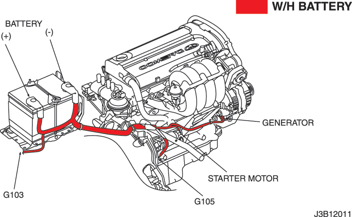
Starting and charging system (starter, generator)
1. Starting and charging system (starter, generator)
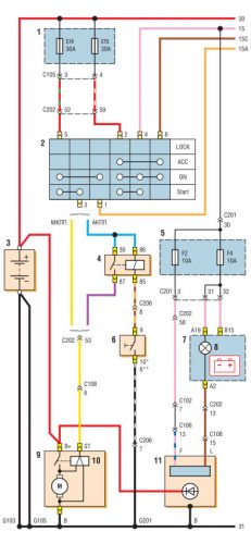
Diagram of generator and starter connections:
1 – the assembly block of the relay and safety locks in a motor compartment; 2 – the ignition switch; 3 – the storage battery; 4 – the relay of blocking of a starter (only with АКП); 5 – the installation block of fuses in the cabin; 6 – the gauge of positions of the selector АКП; 7 – combination of instruments; 8 – the indicator of absence of a charge of the storage battery; 9 – starter; 10 – traction relay starter; 11 – generator;
Battery, ignition, starter, generator and parking / neutral switch circuit
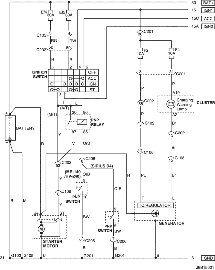
Battery, ignition, starter, generator and parking / neutral switch circuit
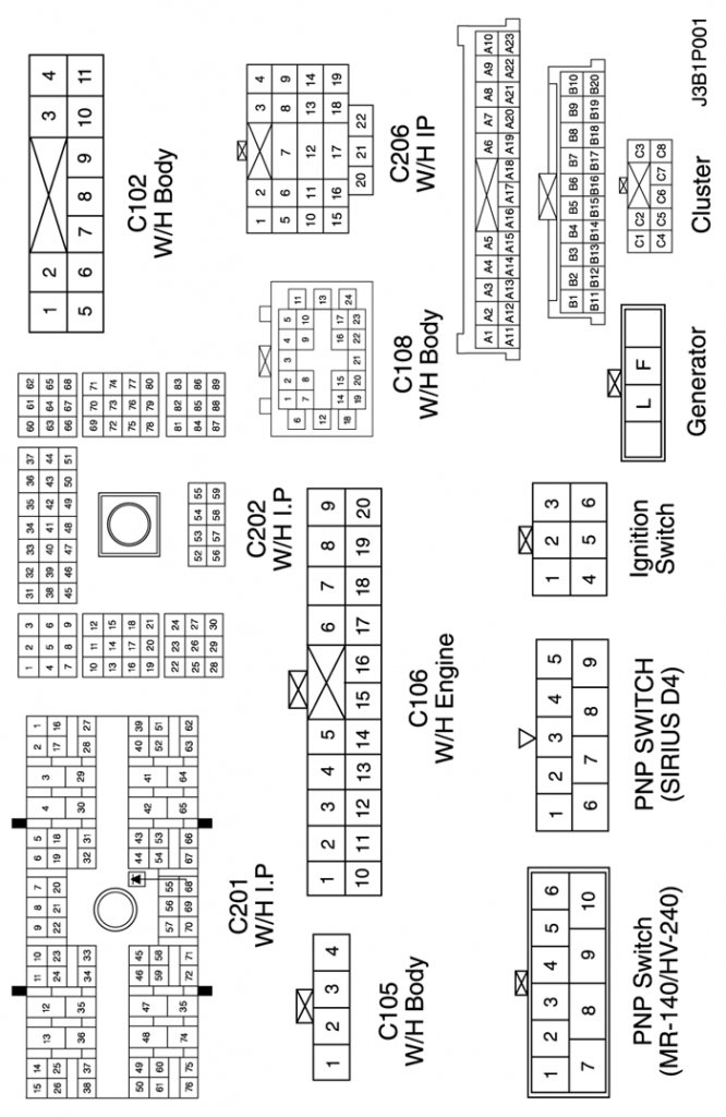
Connector information
| № Connector (№ and contact color) |
Wiring Harness | Connector position |
| With 102 (PIN 11, white) | Body-fuse unit in engine compartment | Fuse unit in engine compartment |
| With 105 (pin 4, white) | Body-fuse unit in engine compartment | Fuse unit in engine compartment |
| With 106 (PIN 20, white) | Engine-fuse unit in engine compartment | Fuse unit in engine compartment |
| With 108 (Contact 24, black) | Body-engine | To the left of the fuse unit in the engine compartment |
| From 201 (Contact 76, black) | Instrument panel-Fuse unit on the dashboard | Fuse unit on the dashboard |
| With 202 (PIN 89, white) | Dashboard-Body | Left part of the driver’s leg space |
| With 206 (Contact 22, white) | Instrument panel-Gearbox controller | Upper part of the driver’s leg space |
| g103 | Rechargeable battery | On the left side of the battery |
| g105 | Rechargeable battery | Under starter |
| g201 | Dashboard | On the left side of the fuse unit on the dashboard |
Symbol & and finding the contact number
Symbol & and finding the contact number
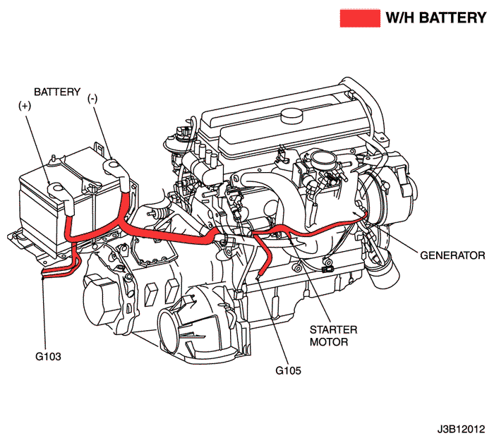
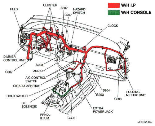
Location of connectors and connections of mass
mr-140/hv-240
sirius d4
dashboard